
When you search for "Magnetic Levitation Kit" on ebay or aliexpress, you'll find offers for a DIY kit for a magnetic levitation platform for around 25 to 40 USD/EUR. I did not find any "official" info for these kits, but I nevertheless ordered one and built it. On this page I collected some info so it will be easier for other to build the kit too.
There are many offers for such a kit, many of them are very similar, but have minor differences. I chose this one.
This kit includes two PCBs, let's call them "electronics PCB" and "magnet PCB":


They are well done and the silk screen makes it quite clear, where all the components belong to. A few notes where it was not completely obvious:
- The 4 electromagnets are screwed into the 4 inner holes from the back. The indented winding orientation is show on the silk screen printing. But I chose to mount them all so that the connecting wires are on top. This way the bottom is flat and can be mounted flush on the PCB. 2 of the electromagnets then have the wrong winding direction. To compensate for this, I flipped the connecting wires.
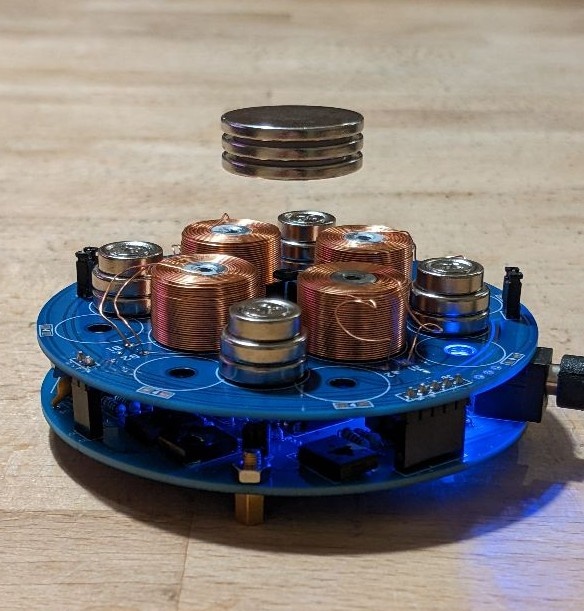
- There are 3 hall sensors. The X and Y sensor are mounted in a right angle to each other. Their upper edge should be at the same height as the vertical center of the electromagnets. The third hall sensor is bent over and lies on top of the other 2 hall sensors. See photo below.
- My kit contained 4 permanent magnets stacks, each consisting of 3 individual disc magnets. The magnet PCB has 12 holes for permanent magnet stacks, each quadrant has 3 holes. I think the PCB can be used for configurations with 4 or 8 magnet stacks. For 4 stacks, use the central hole in every quadrant for each stack, for 8 stacks leave out the central holes and use the others.
- The permanent magnets are mounted all in the same (magnetic) orientation.
- On the magnet PCB there are pads for soldering LEDs forming a ring at the outer edge of the PCB, and pads for a switch. These components are not included in my kit, I simply left them unpopulated.
- On the magnet PCB there two 2-pin-headers for jumpers. The kit includes right-angled headers, but I chose to use straight pin headers instead. This way they do not extend beyond the edge of PCB which makes it easier to fit it into a enclosure.
- On the electronics PCB, there is a footprint for an LED next to the power adapter. The footprint looks like it is for a standard 5mm LED, but the kit includes a square LED.
- The 2 PCBs are connected with 4 pin headers, a 5-pin, a 4-pin and two 2-pin headers. The electronics PCB is the lower one, with the components facing up. Therefore, the female connectors go on the component side of the electronics PCB, the male connectors on the underside of the magnet PCB.
The populated PCBs look like this:


(Note I added sockets for the ICs, but used 16 pin sockets instead of 14 pin sockets cause this is all at had lying around. Don't let the extra pins confuse you)
User sdg12832 analyzed the circuit at posted a schematic diagram on this Russian website. This is what he came up with:

He also wrote about how he calibrated the circuit. I used a slightly different method:
- Power up the circuit. The LED will not turn on (or only light up shortly). This is normal, the magnets will only be powered up when the levitating magnet is placed on top.
- When not calibrated correctly, the circuit will draw a lot of power and the electromagnets and the transistors will get very hot quickly. Do not let it powered up in that state for a long time.
- Remove both jumpers on the magnet PCB. This will disable both the X and the Y electromagnets, X being the 2 electromagnets for the horizontal and Y the 2 in vertical direction.
- Take a multimeter, switch it to DC ampere mode and connect to the 2 pins of one of the headers where the jumpers have been. This will enable one of the two directions and display the current on the multimeter. Make sure your multimeter can handle 3 A.
- Cover the device with something to prevent the levitating magnet from crashing into it. Really, do it! It will happen!
- Hold the levitating magnet over the center of the device. The right orientation is the one when it is repelled by the permanent magnets. The magnet will try to escape sideways. The circuit should now turn on, the LED should light up.
- Try to get the magnet over the exact center of the device. At the same time, check the current and use a small screwdriver to turn one of the blue potentiometers to get the current as close as possible to 0. This is best done with two persons. The current can flow in both directions, pay attention to the sign of the displayed current. If turning the potentiometer does not change the current, you probably have the wrong one, try the other one.
- When you have finished this, remove the multimeter from the pins and connect it to the other pin headers. Now perform the same procedure again, this time using the other potentiometers.
- Now remove the multimeter and put the jumpers in again. Now you should be able to levitate the magnet over the center. If it does not work, repeat the calibration.
- For fine tuning the calibration, you can replace one (only one!) of the jumpers with the multimeter and again try to get the current to 0 while the magnet is levitating. Repeat with the other jumper/potentiometer.
Enclosure (for 3D printing, designed by me):
