...
- Please see included STEP file where the individual parts go.
- Start with assembling the "end plates". They are made of 3 layers of lasercut aluminium, which are aligned and held together by M3 screws and M3 on the inside. These screws and nuts are not included in the STEP.
- The wheels (we need 8 for build) consist of 4 parts: The wheel itself, 2 ball bearings and a shim. The shim goes between the 2 ball bearings. The wheel package can contain an addition shim and a lock nut, which are NOT needed for the wheels. Also see wheel build video here: https://openbuildspartstore.com/xtreme-solid-v-wheel-kit/
- The lasercut holes in the aluminium plates are often too small. Drill them out to have the right sizes so that the screws go through. The only exception are 4 holes in the bed plate:
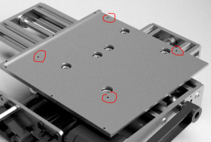
These holes need an M3 thread to be cut into. Use M3x5 screws to bolt the upper sled plate to the bed plate using these threaded holes. - There are different types of slot t-nuts, : slide-in and drop-in types. The slide-in type can only be inserted from the ends of the profile. If you have these types, make sure you insert the t-nuts at the right places before screwing on the endplates, otherwise they cannot be inserted any more. There are 4 t-nuts in the bottom slots of the assembly, they are used to fix the table in the Laser4DIY device later. Make sure you add these t-nuts now too.
- The wheels are attached with 6mm spacers, with standard spacers on one side and eccentric spacers on the other side of the sled. The eccentric spacers can be used to increase the force the wheels press onto the beams.
- Make sure the motor orientation is correct, i.e. the cable connector is on the right side. See STEP file.
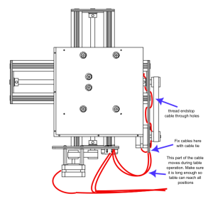
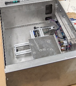
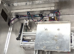
- Wires: see the following diagram and photos
Electronics
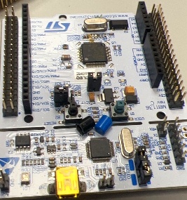
The CNC controller consists of a Nucleo STM32F446 board, a CNC shield and 2 TMC2100 SilentStepStick stepper driver boards.
- The CNC shield is inserted into the Arduino connector of the Nucleo board
- Pay attention to the two micro switches on the Nucleo board located under the CNC shield. Some Nucleo boards (all?) have quite tall caps on these switch, which touch the CNC shield and are therefore pressed down all the time! As one of the switches is the reset button this will prevent your board from functioning. To avoid this, remove the caps from the switch:
- There should be no jumpers on the CNC shield
- The SilentStepStick drivers are inserted into the CNC shield (for axis X and Y). Make sure, that the orientation is correct (see image below). A wrong orientation will destroy the driver.
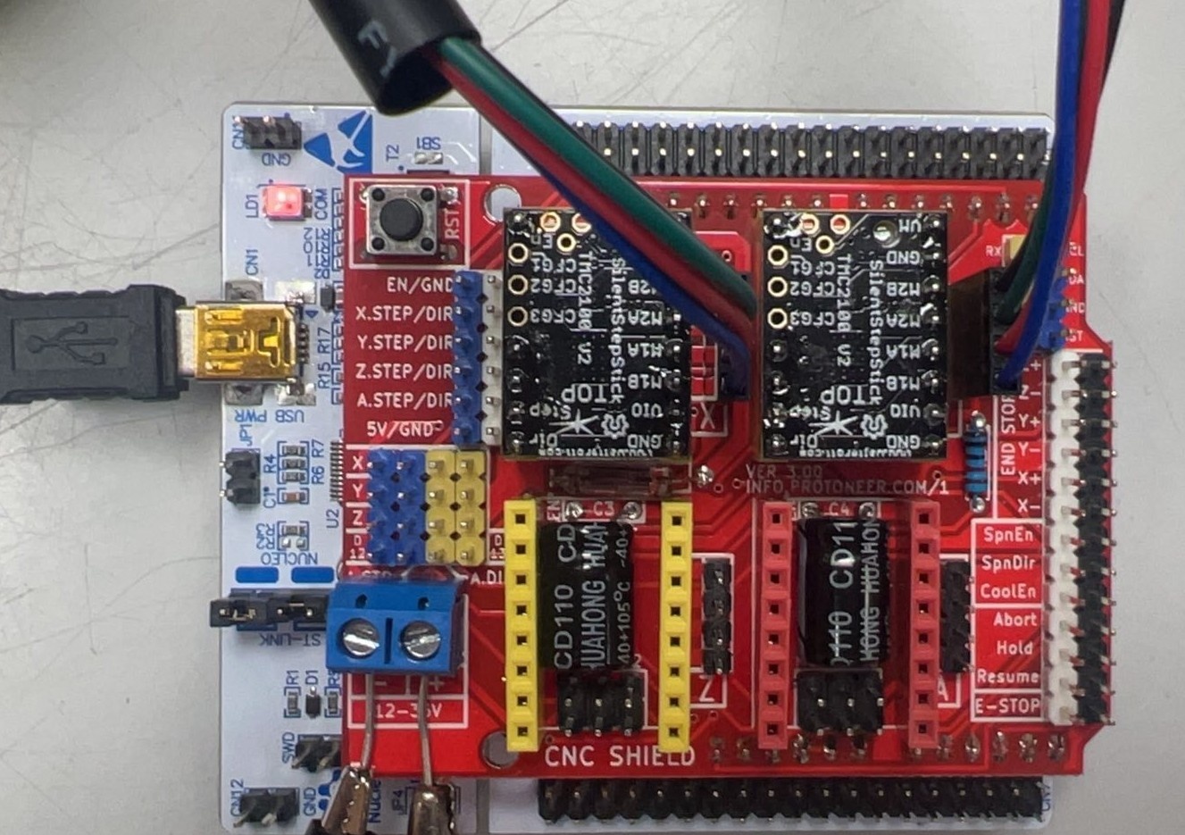
Nucleo board with CNC shield and stepper drivers. In this picture the EN pin of the SilentStepStick drivers is on the top left, the GND pin is on the bottom right
Configuring the TMC2100 stepper drivers
...