Introduction
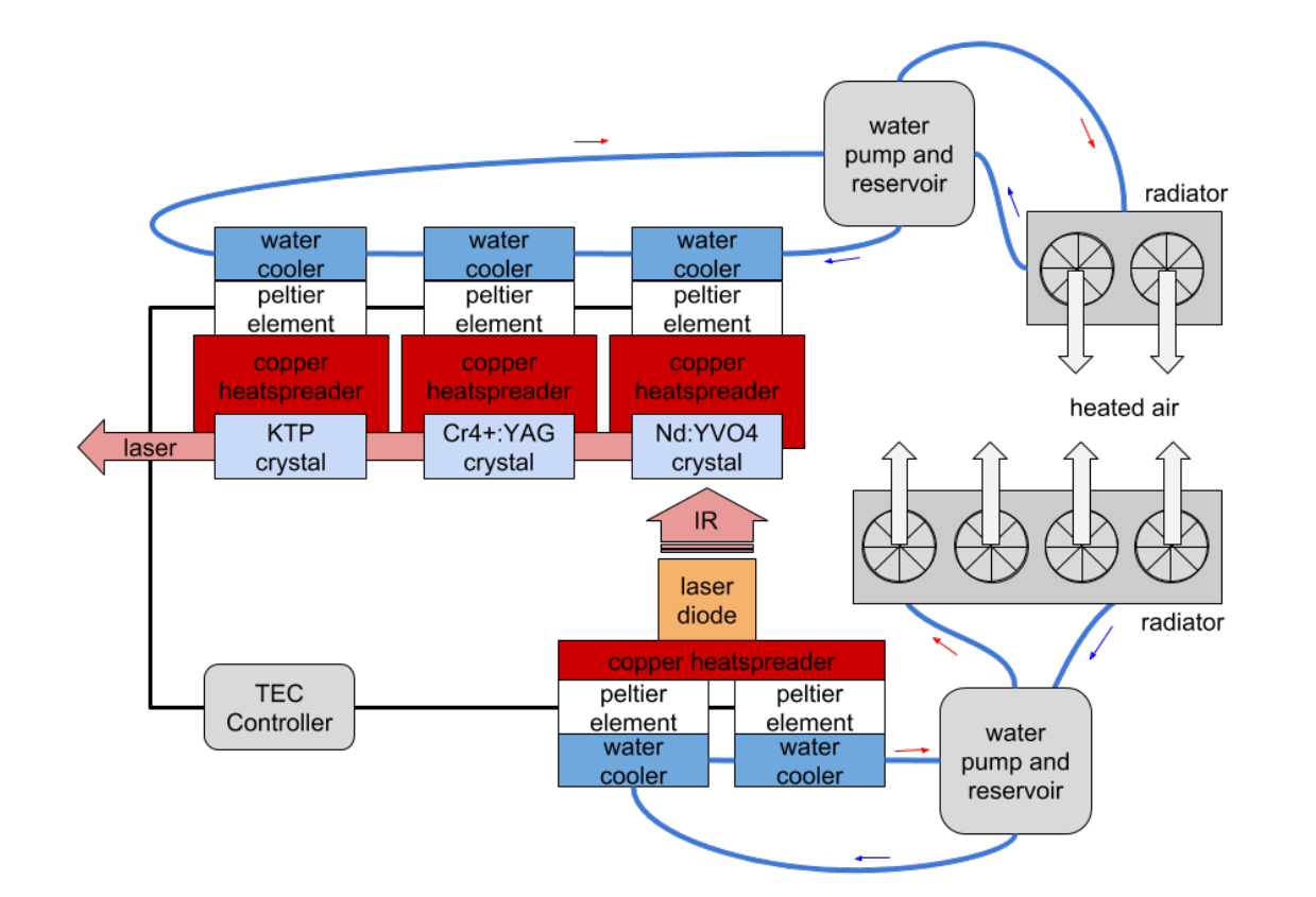
An important part of the Laser4DIY system is the cooling system. There are four components that need to be actively cooled: the laser disode, the KTP crystal, the Cr4+:YAG crystal and the Nd:YVO4 crystal. The laser diode is the component which the most demanding cooling requirements as it produces a lot of waste heat but at the same time needs to be held at a constant temperature to avoid fluctuations in wave length of the produced laser light.
Our appraoch is a low-cost cooling setup which combines the precision of thermoelectrical controlled cooling with the low cost of off-the-shelf CPU cooling components. As one can see in the figure below two cooling loops are used, one for the laser diode and one for the crystals.
Requirements and Similar Projects
The requirements for the temperature controller or more accurate TEC-Controller (TEC stands for thermo electric cooling and utilizes peltier elements to cool or heat without any moving parts) are coming from the project requirements themselves and the technical requirements for being able to cool the laser sufficiently. The general requirements are:everything has to be published as open source, every component has to be suitable to be soldered to the corresponding PCB by hand and finally it has to be as cost-saving as possible. The technical requirements are: being able to control four peltier elements simultaniously with 106W heat transfer capacity, which means to switch 12A at 15.5V. Furthermore it should be able to stabilize temperature of a laser diode within 0.3 K. A similiar concept of a low-power open-source TEC-controller is already available at http://hololaser.kwaoo.me/electronics/Arduino_TEC/Arduino-TEC.html. The concept of the TEC-Controller developed for Laser4DIY is derived from this project, but heavily modified to meet the requirements. The core platform has been changed from Arduino Uno to Arduino Due. In course of that the voltage of the digital signals changed from 5V to 3.3V, which meant to change all other components to work with the lower voltage. The reason behind that is, that for four channels the Arduino Uno has not enough computing power to run the PID controller in software and not enough pins to run the switching hardware. Furthermore the power part of this particular TEC-Controller was designed to drive only small peltier elements with currents up to 3A, which is not enough for this project.
Principle of Temperature Control
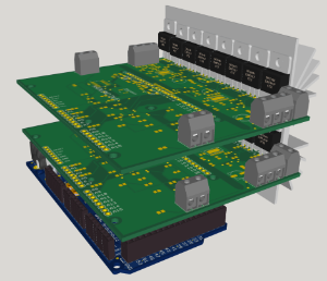
The principle of temperature control is very simple: There is an input screw terminal, to which a NTC (negative temperature coefficient) resistor, which is a component with temperature-dependent resistance, is connected. This NTC should be thermally coupled very strongly to the object whose temperature is intended to be be regulated. The temperature is read out over the microcontrollers ADC and compared in software with the setpoint. The software then steers the output controlled by a PID algorithm. The output is a PWM (pulse width modulated) signal, which means that it is a square wave with fixed frequency but varying duty cycle. This signal is used by a H-bridge controller to drive the gates of four MOSFETs in H-bridge configuration. The output of those is connected to a screw terminal where the peltier element can be connected to. This whole control circuit is twice on one board and with two boards stacked on each other the Arduino Due has four control channels in total. Both boards are identical in design and can be configured to act as board with channels 1 and 2 or as board with channels 3 and 4 via solderbridges.
2. Einordnung ins Gesamtsystem (da hab ich ein, zwei gute Diagramme in der Masterarbeit)
3. Deeper Background/Development (General Setup: Component Selection, Component Design, Schematic und Layou)
4. Zusammenbau (coming soon)
5. Software