 Image Removed
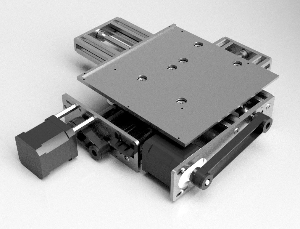 Image Added
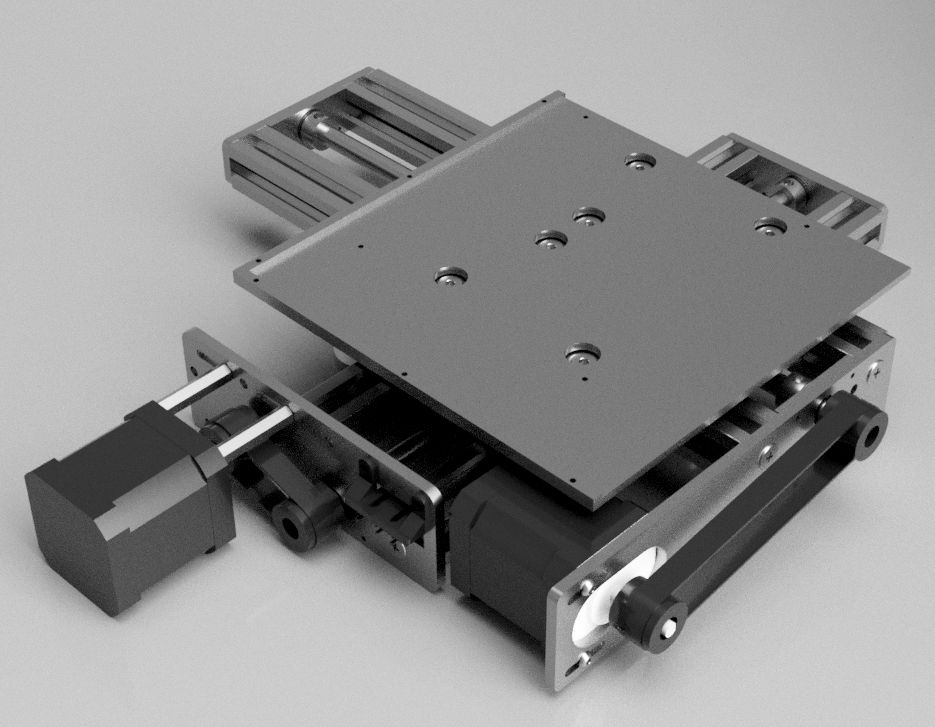
- Table Size: 165mm x 165mm
- Overall Size: 278mm 368mm x 333mm x 56mm (with pancake motor)
- Based on 2 OpenBuilds NEMA17 V-Slot Actuators with Lead ScewScrew
Files
See https://github.com/Laser4DIY/XY-Table
License
The Laser4DIY XY Table is licensed under the CERN-OHL-P v2.This is work in progress!
Parts List
Off-the-shelf parts
| Qty | Part Name | Part Link | Comments |
|---|
| 2 | 8mm Metric Acme Lead Screw 290mm |
http:///8mm-metric-acme-lead-screw/http:///anti-backlash-nut-block-fo...https:///linear-rail/13-linear-rail-20x20-v-slot.html Wheel™ http:///xtreme-solid-v-wheel-kit/http:///aluminum-spacers/http://openbuildspartstore/eccentric-spacer/ | SKU 226 |
| 4 | Ball Bearing 688Z 8x16x5 |
http://openbuildspartstore.com/ball-bearing-688z-8x16x5/http:///8mm-shim/http://openbuildspartstore/lock-collar/5https://openbuildspartstore.com/tee-nuts-m5-10-pack/http://openbuildspartstore.com/low-profile-screws-m5/https://openbuildspartstore.com/thin-hex-nut-m5/| openbuildspartstore.com ratrig.com | SKU 181; for mounting wheels |
| 5 | M5 x 8mm Button Head Screw |
|
|
| 11 | M3 x 8mm Button Head Screw |
|
|
| 4 | M3 x 5mm Button Head Screw |
| For screwing SledPlate to BedPlate |
| 10 | M3 Nut |
|
|
| 6 | M2 x 6mm Screw |
| for attaching the "ruler" |
| 4 | M2 x 10mm Screw |
|
|
| 10 | M2 Nut |
|
|
| 2 | M2 Washer |
|
|
| 8 | Self Tapping Screw #10 |
http:///self-tapping-screw/| ratrig.com | SKU 720 |
| 3 | Hex Standoff M3 (female/male) 30mm |
| For mounting one of the stepper motors |
| 2 | NEMA 17 Stepper |
Motorhttps:///nema-17-stepper-motor/| ratrig.com | Use pancake motor to save space (mandatory to fit into Laser4DIY enclosure) |
| 2 | GT2 pulley 20 5mm bore |
https:///belts-and-pulleys/479-belts-and-pulleys-mellow-gt2-pulley-20.htmlhttps:///belts-and-pulleys/479-belts-and-pulleys-mellow-gt2-pulley-20.html| |
|
| 1 | GT2 timing belt 6 mm closed loop 128 mm |
https:///GT2-Zahnriemen-6-mm-128-mm-64-Zaehne |
|
| 1 | GT2 timing belt 6 mm closed loop 250 mm |
https:///GT2-Zahnriemen-6-mm-250-mm-125-Zaehne |
|
| 2 | Micro Switch |
| Panasonic AV32143AT or similar |
Custom parts
| Qty | Part Name | Process | Material | File |
|
|---|
| 2 | StandardEndPlate_BeamBracket | Laser cutting | Aluminium (AlMg3), 2mm | 2mm_ALL_with_tabs.dxf |
|
| 2 | StandardEndPlate_InnerPart | Laser cutting | Aluminium (AlMg3), 2mm | - " - |
|
| 2 | StandardEndPlate_OuterPart | Laser cutting | Aluminium (AlMg3), 2mm | - " - |
|
| 1 | EndPlateLower_BeamBracket | Laser cutting | Aluminium (AlMg3), 2mm | - " - |
|
| 1 | EndPlateLower_InnerPart | Laser cutting | Aluminium (AlMg3), 2mm | - " - |
|
| 1 | EndPlateLower_OuterPart | Laser cutting | Aluminium (AlMg3), 2mm | - " - |
|
| 1 | EndPlateUpper_BeamBracket | Laser cutting | Aluminium (AlMg3), 2mm | - " - |
|
| 1 | EndPlateUpper_InnerPart | Laser cutting | Aluminium (AlMg3), 2mm | - " - |
|
| 1 | EndPlateUpper_OuterPart | Laser cutting | Aluminium (AlMg3), 2mm | - " - |
|
| 1 | BedRuler | Laser cutting | Aluminium (AlMg3), 2mm | - " - |
|
| 2 | SledPlate | Laser cutting | Aluminium (AlMg3), 3mm | 3mm_ALL_with_tabs.dxf |
|
| 1 | BedPlate | Laser cutting | Aluminium (AlMg3), 3mm | - " - |
|
| 2 | SledSpacer | Laser cutting | MDF, 5mm | 5mm_sledspacer.dxf | Could also be aluminium |
| 1 | Microswitch Bracket | 3d printing | any plastic e.g. PLA | MicroswitchBracket.stl |
|
| 1 | Microswitch Bracket 2 | 3d printing | any plastic e.g. PLA | MicroswitchBracket.2stl |
|
...
The "end plates" are made of 3 layers of lasercut aluminium, which are aligned and held together by M3 screws. It is also possible to have them CNC milled as on one piece, but we choose chose laser cutting as it is much cheaper to get them produced this way.
Driver Electronics
| Qty | Part Name | Part Link | Comment |
|---|
| 1 | Nucleo STM32F446 (STM32F446RET6) | http://www.st.com/stm32nucleo | Documentation,
Manual |
| 1 | CNC Shield (for Arduino Uno) | https://blog.protoneer.co.nz/arduino-cnc-shield/ | Schematic |
| 2 | SilentStepStick TMC2100 stepper driver |
| other, compatible stepper drivers can be used, too |
| 14 | Dupont connector female |
| You need 2 x 4pin connectors for the stepper motors and 3 x 2pin connectors for the endstops and laser enable signal.
We simply used jumper cables and extended/soldered them to the cables coming from the steppers/endstops. |
Overall Size
The overall size of the table is larger than its components, as the table moves beyond their extents. The following drawing shows how much space is needed. The aluminum extrusions of the lower rail (vertical in the drawing) are the ones that should be fixed e.g. to a mounting plate using brackets or V-slot T-nuts.
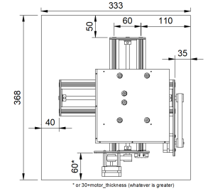 Image Added
Assembly
- Please see included STEP file where the individual parts go.
- Start with assembling the "end plates". They are made of 3 layers of lasercut aluminium, which are aligned and held together by M3 screws and M3 on the inside. These screws and nuts are not included in the STEP.
- The wheels (we need 8 for build) consist of 4 parts: The wheel itself, 2 ball bearings and a shim. The shim goes between the 2 ball bearings. The wheel package can contain an addition shim and a lock nut, which are NOT needed for the wheels. Also see wheel build video here: https://openbuildspartstore.com/xtreme-solid-v-wheel-kit/
- The lasercut holes in the aluminium plates are often too small. Drill them out to have the right sizes so that the screws go through. The only exception are 4 holes in the bed plate:
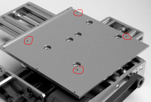 Image Added
These holes need an M3 thread to be cut into. Use M3x5 screws to bolt the upper sled plate to the bed plate using these threaded holes. - There are different types of slot t-nuts: slide-in and drop-in types. The slide-in type can only be inserted from the ends of the profile. If you have these types, make sure you insert the t-nuts at the right places before screwing on the endplates, otherwise they cannot be inserted any more. There are 4 t-nuts in the bottom slots of the assembly, they are used to fix the table in the Laser4DIY device later. Make sure you add these t-nuts now too.
- The wheels are attached with 6mm spacers, with standard spacers on one side and eccentric spacers on the other side of the sled. The eccentric spacers can be used to increase the force the wheels press onto the beams.
- Make sure the motor orientation is correct, i.e. the cable connector is on the right side. See STEP file.
- Wires: see the following diagram and photos
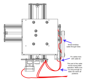 Image Added
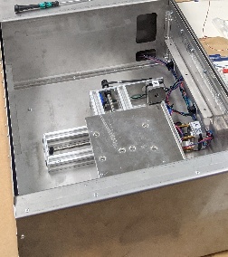 Image Added
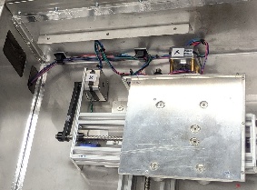 Image Added
Electronics
The CNC controller consists of a Nucleo STM32F446 board, a CNC shield and 2 TMC2100 SilentStepStick stepper driver boards.
- The CNC shield is inserted into the Arduino connector of the Nucleo board
- Pay attention to the two micro switches on the Nucleo board located under the CNC shield. Some Nucleo boards (all?) have quite tall caps on these switch, which touch the CNC shield and are therefore pressed down all the time! As one of the switches is the reset button this will prevent your board from functioning. To avoid this, remove the caps from the switch:
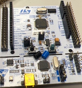 Image Added
- There should be no jumpers on the CNC shield
- The SilentStepStick drivers are inserted into the CNC shield (for axis X and Y). Make sure, that the orientation is correct (see image below). A wrong orientation will destroy the driver.
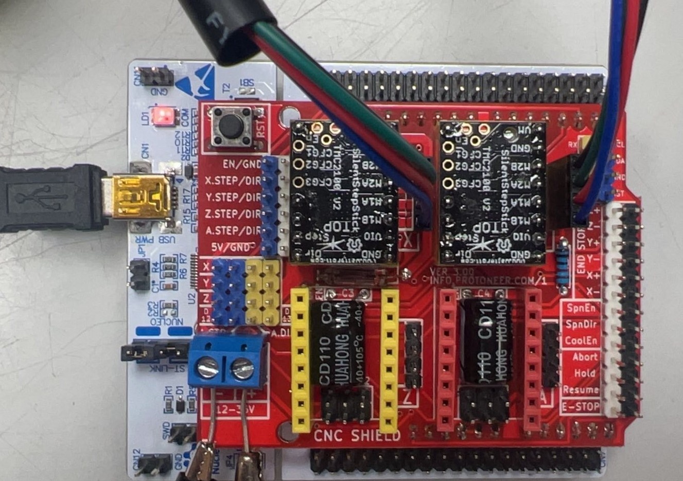 Image Added
Nucleo board with CNC shield and stepper drivers. In this picture the EN pin of the SilentStepStick drivers is on the top left, the GND pin is on the bottom right
Configuring the TMC2100 stepper drivers
- https://learn.watterott.com/de/silentstepstick/pinconfig/tmc2100/
- 1/16 mcrostepping, 1/256 interpolation, stealthChop → CFG1 open + CFG2 open + CFG3 open
- We suggest to simply not solder in the CFG1-3 pins, this way the config is fixed to this setup
Connecting XY table with CNC shield
| Function | CNC Shield Label | Wiring |
|---|
| Stepper X | X | 4 wires to stepper, ordered of the pins is the same as described in TMC2100 data sheet |
| Stepper Y | Y | 4 wires to stepper, ordered of the pins is the same as described in TMC2100 data sheet |
| Endstop X | X+ | 2 wires (signal + ground) to end switched, configured as normally-open |
| Endstop Y | Y+ | 2 wires (signal + ground) to end switched, configured as normally-open |
| Laser Enable | Z+ | 2 wires (signal + ground) to laser driver electronics |
Firmware
We are running an enhanced version of GRBL with the XY table, called GRBL-Advanced. It runs on a STM32F411RE / STM32F446RE Nucleo Board and offers backlash compensation to archive better precision.
You can find the Github repository with our fork here: https://github.com/Laser4DIY/GRBL-Advanced
- Ready to use Binary: https://github.com/Laser4DIY/GRBL-Advanced/tree/software/hex
- Build your own binary:
- Flash firmware onto Nucleo:
- right click bin/Release/GRBL_Advanced.hex, select EBlink Cortex-M → Flash File
- or via cmd line: eblink -F erase,file=GRBL_Advanced.hex
- unplug and replug board
- Test: connect to COM port with 115200 baud
Configuring
To configure GRBL Advanced, please see here: Configuring GRBL Advanced
We are using Lightburn to control the table in the Laser4DIY device. See Configuring Lightburn on how to set it up correctly.
Results
We measured around 0,05mm of backlash for the XY table in both directions. But with the backlash compensation feature, some impressive results are archivable. Here is an example engraving done with our Laser4DIY machine:
 Image Added
 Image Added
Please note that letters are not a single line, the outlines are engraved.
Here is a microscope shot of an engraving with a font ~0.5mm high:
 Image Added
...
Copyright FabLab München e.V. 2021
This source describes Open Hardware and is licensed under the CERN-OHL-P v2
You may redistribute and modify this documentation and make products using it under the terms of the CERN-OHL-P v2 (https:/cern.ch/cern-ohl).
This documentation is distributed WITHOUT ANY EXPRESS OR IMPLIED WARRANTY, INCLUDING OF MERCHANTABILITY, SATISFACTORY QUALITY AND FITNESS FOR A PARTICULAR PURPOSE.
Please see the CERN-OHL-P v2 for applicable conditions