
We have received and finally open the Educational Kit, Thanks to the support of RS-Components.
The kit with all the tutorial can be found on the rs-online page, here the nice picture with Massimo Banzi that you know.
I posted here also the list of the videos because the projects are really whell defined from the simplest one to a lamp that can be controlled via twitter.
...
But back to the educational kit,
it it has a very complete set of different components, that allow a lot of different experiments:
...
The kit has a very well done book with a lot of pictures that help the understanding of the different devices and the connectivity on the breadboard

The kit has a lot of components also in quantity, like the 6 photoresistors.
...
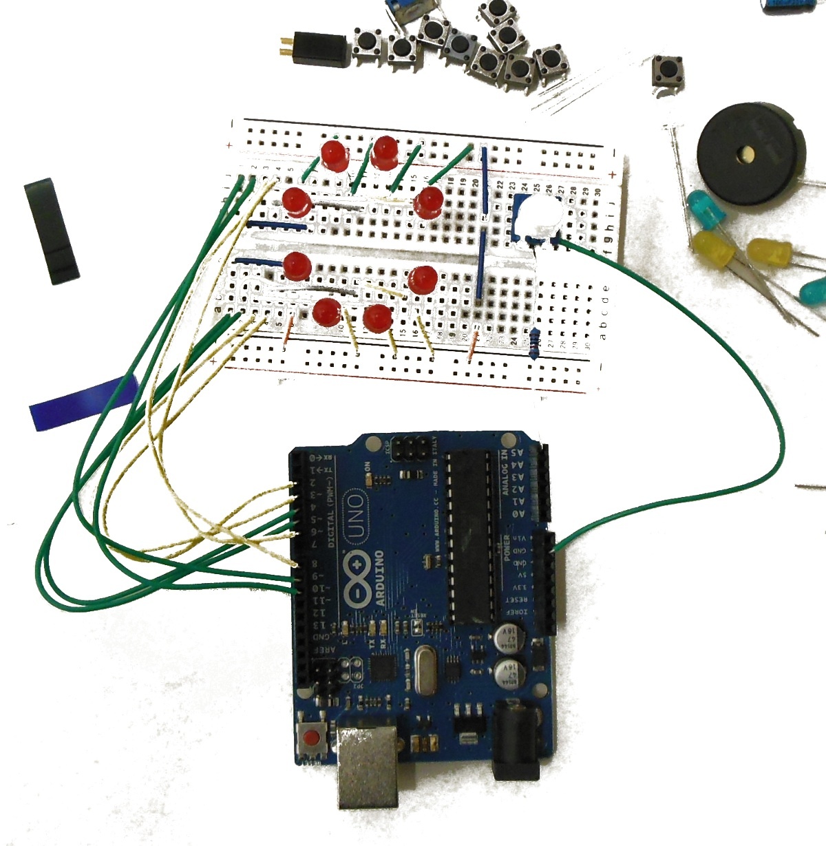
To start I placed a set of LED in a circle and I connected them to Arduino:
| Section | ||||||||||||||||||
|---|---|---|---|---|---|---|---|---|---|---|---|---|---|---|---|---|---|---|
| ||||||||||||||||||
| width | 320
|
The code is very simple, I connected the LED in sequence starting from port 2 to port 9,
...
| Section | ||||||||||||||||||||||
|---|---|---|---|---|---|---|---|---|---|---|---|---|---|---|---|---|---|---|---|---|---|---|
| ||||||||||||||||||||||
|
The code is a bit more complicated,
...
| Note |
|---|
#include <Servo.h> .... Servo myservo; ..... void setup(void) { .... myservo.attach(10); .... } void loop(void) { |
TO To start to get familiar with the kit I decided to create something simple, using some of the most standard components ,
I created a LED visualisation visualization system for the position of a servo .
To start I placed a set of LED in a circle and I connected them to Arduino:
| Section | ||||||||
|---|---|---|---|---|---|---|---|---|
| ||||||||
|
It is needed also to compensate the rotation , because the servo is rotating only of 180' and the variable resistance of ~300' and the LED of 360'
It is needed to adjust the values. The code is also not very efficient , because it uses a list of if statement,
it could be concerted few lines of code , using bit shift functions and a threshold function.
This will be for the next time.
Here attached my code:EDUCATIONAL_led_round.ino
...