We have received and finally open the Educational Kit,
it has a very complete set of different components, that allow a lot of different experiments:
 |
|  |
|  |
|
The kit has a very well done book with a lot of pictures that help the understanding of the different devices and the connectivity on the breadboard

The kit has a lot of components also in quantity, like the 6 photoresistors.
 |
|  |
|
To start to get familiar with the kit I decided to create something simple, using some of the most standard components,
I created a LED visualization system for the position of a servo.
To start I placed a set of LED in a circle and I connected them to Arduino:
| Section | ||||||||
|---|---|---|---|---|---|---|---|---|
| ||||||||
|
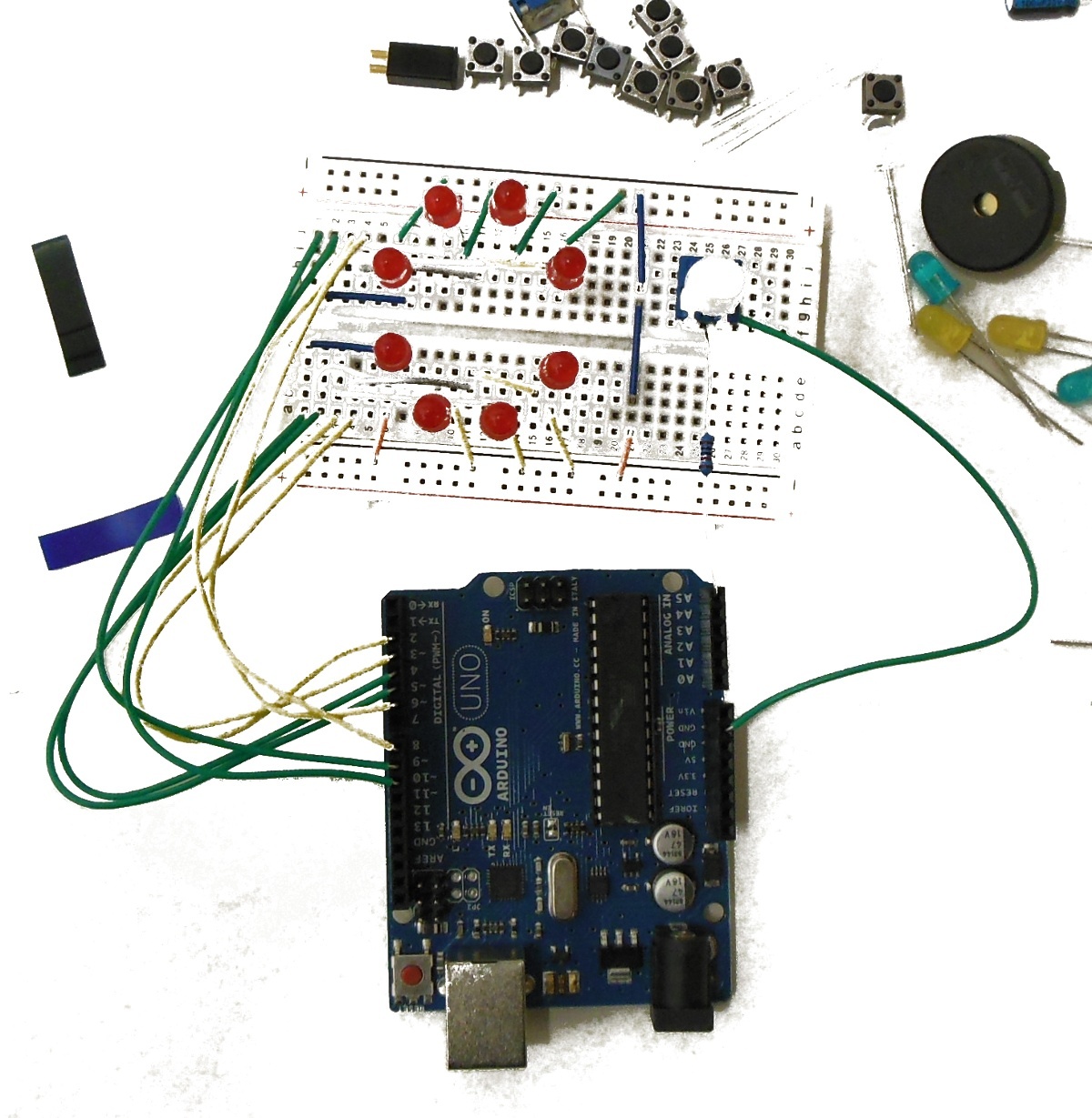
The code is very simple, I connected the LED in sequence starting from port 2 to port 9,
the LED0 is equal to 2 and I am starting looping on 2 to 9 and resetting the previous LED,
using the prev variable .
| Note |
|---|
for(j=0;j<2;j++) { if (i!=0) {prev=i-1;} else {prev=9-2;} digitalWrite(LED0+prev,LOW); |
Second step of the example is to control the LED using the variable resistance ,
to do that first you need to connect the resistor to one analog input and send the reading to the serial port for Arduino
to display it , here you can see the video of my tests on the serial port reading , and the final results:
| Section | ||||||||||||||||||
|---|---|---|---|---|---|---|---|---|---|---|---|---|---|---|---|---|---|---|
| ||||||||||||||||||
|
The code is a bit more complicated,
you need to read the analog input and send the results on the serial port ,
read the values with the monitor and adjust the min max values based on what you read,
in my case the min was 0 and the max was 470.
| Note |
|---|
val=analogRead(A5); if (val>r0L && val<r0H) { all_off; digitalWrite(LED7,HIGH); } |
I am using a lot of define because I like them , the analog reading "val"
is compared to the different thresholds that are stored in the initial define
like also the LED port numbers ..
| Note |
|---|
#define LED0 2 #define r0L 0 #define all_off digitalWrite(LED0,LOW); digitalWrite(LED1,LOW); digitalWrite(LED2,LOW); digitalWrite(LED3,LOW); digitalWrite(LED4,LOW); digitalWrite(LED5,LOW); digitalWrite(LED6,LOW); digitalWrite(LED7,LOW); |
Last step is to add the needed servo infrastructure and drive not only the LED but also the servo with
the correct angle . The program is not finish and should be adjusted becasue the servo can rotate only 180 degree,
but the LED are rotating 360 degree , I need to turn on two LEDs together
| Note |
|---|
#include <Servo.h> .... Servo myservo; ..... void setup(void) { .... myservo.attach(10); .... } void loop(void) { |
TO start to get familiar with the kit I decided to create something simple, using some of the most standard components ,
I created a LED visualisation system for the position of a servo .
To start I placed a set of LED in a circle and I connected them to Arduino:
| Section | ||
|---|---|---|
| ||