Creating Tool Paths
The first step is to create tool paths to be run on the Laser4DIY device. This is very similar to isolation milling, we just replace the milling tool with a laser. Therefore, we can use software suitable for PCB isolation milling. In this tutorial, we use FlatCAM, an open source tool, which can also import Gerber files. There is also a tutorial on the FlatCAM site.
Import GCode
- Open FlatCAM
- File → Open Gerber
- Load the top CU layer

Setup Tool
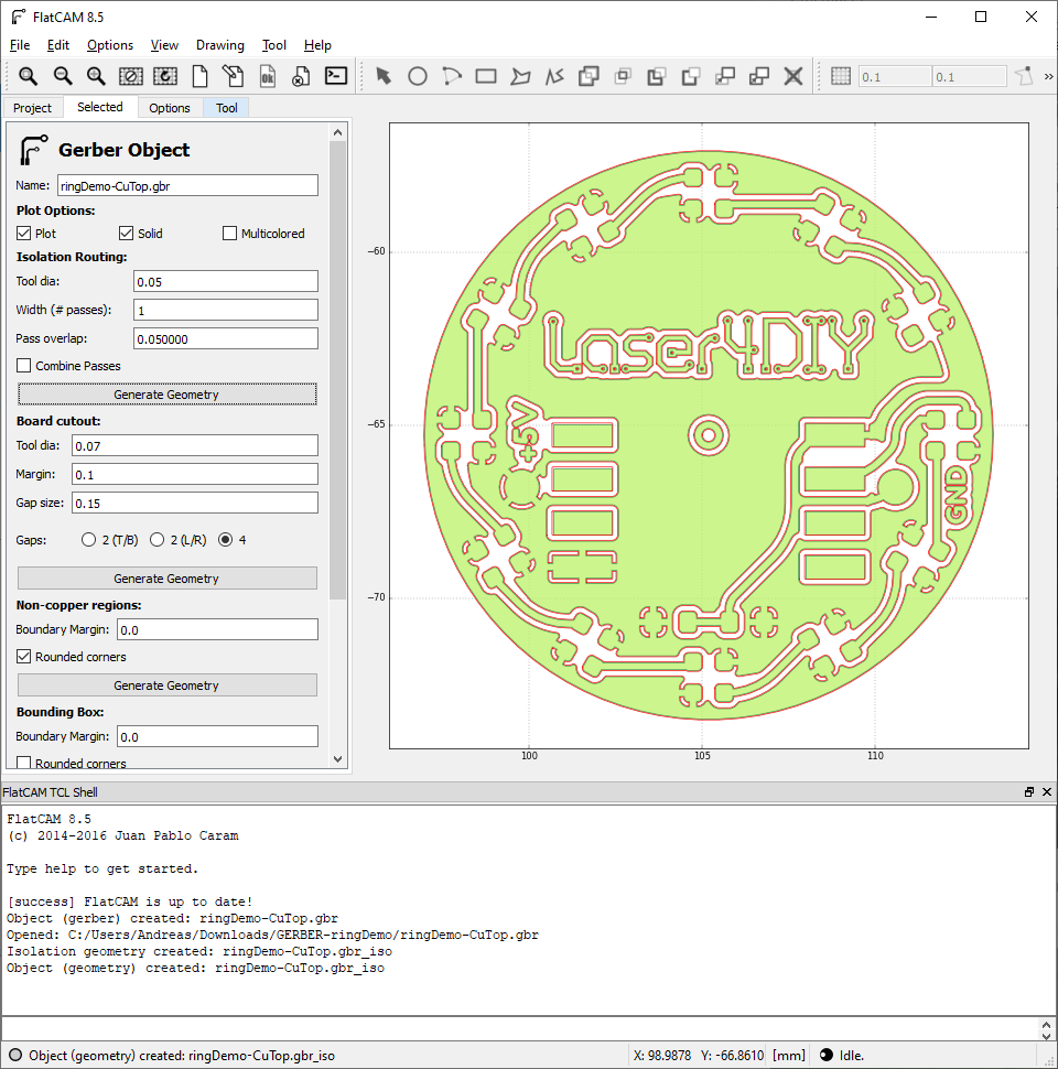
- Select Gerber layer in project tab
- Switch to 'Selected' tab
- Set tool dia to 0.05
- Set to 1 pass

Create Geometry
- Press the "Create geometry" button
- The red lines around every trace indicate where the laser will ablate copper
Save SVG and Cleaning it Up
- Go back to the Project tab
- there now should be a new iso entry
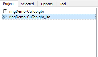
- Select it
- Choose File → Export SVG
- The now should be an SVG file exported with the tool path
- Open the SVG in Inkscape to check if everything worked as expected
- When you only see a blank white canvas, it can be that all geometry is outside the document
- press 4 (or select View → Zoom → Zoom Drawing) to change the viewport to the drawing
- to move everything onto the canvas:
- Ctrl+A to select everything
- Ctrl+X to cut it
- 5 to view the document
- Ctrl+V to paste it
- Move the drawing on the document, make sure snapping mode is on
- Make all lines hairlines
- Ctrl+A to select everything
- Object → Fill and Stroke...
- In Stroke Style tab select Hairline
- Save SVG again

Running ToolPath in Lightburn
The Laser4DIY device can be controlled by any software that supports Grbl. We are using Lightburn. The following steps are Lightburn specific, for other software packages, corresponding steps have to be performed.
Lightburn initially has to be configured to use the Laser4DIY device. Please refer to this guide for doing so.
Loading SVG
The generated toolpath can simply be loaded by drag-n-dropping it into the workspace:
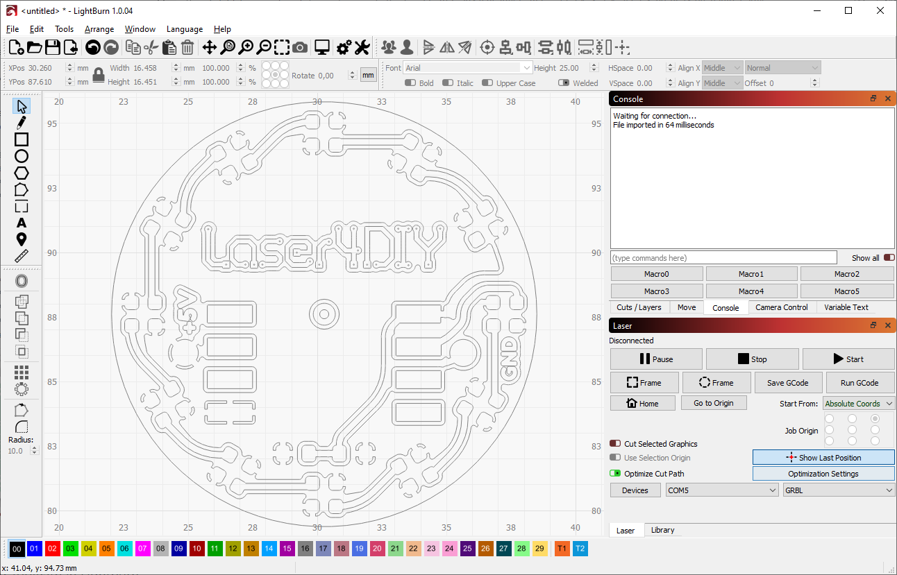
Placing Toolpath at Right Position
- You can move the toolpath to the correct position (where the PCB material lies on the XY table) by simply dragging it
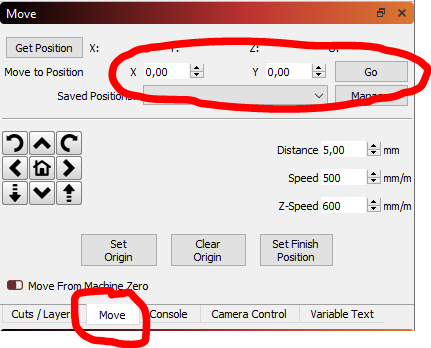
- In the 'Move" section you can enter coordinates to check if the positioning is correct. Use coordinates shown on the workspace view

- Alternatively you can use the "Frame" feature
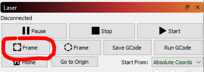
- Please note that the Laser4DIY device does not have a pilot laser. Positioning by eye cannot be done exactly therefore.
- We recommend using a PCB blank a bit larger than needed
- If you need exact placement (e.g. for two sided PCBs), you can use stops of the table. Please make sure you have adjusted the end stops precisely if you want to rely on them
Setting Speed
The output power of the Laser4DIY device varies, depending on how much power your seed laser diode emits and how well your device is tuned. Depending on that the ablation speed needs to be adjusted. A speed of 15 mm/min worked well for us, but we recommend doing some small tests before starting a big PCB job. Doing 2 faster passes (2 passes with 30 mm/min each) can produce better results, but in this case backlash compensation has to be tuned very precisely so that the second pass ablates at exactly the same position again.
In Lightburn, you set the speed in the Cut/Lasers tab.
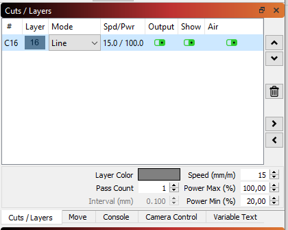
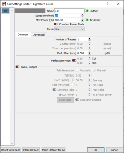
By double clicking the speed, another dialog comes up, allowing to change the details. Leave the power setting at 100%, smaller values will not actually change the laser power. Also leave on "Output" and "Show". "Air" does not have any effect.
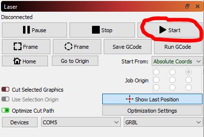
Running the job
Finally, close the lid of the Laser4DIY and start the job. This is done by hitting the Start button
Lightburn will display a progress bar for the ablation process